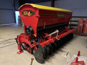
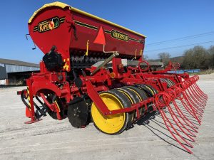
I have owned this drill for almost 10 years and to be fair it had done a lot of work when I bought it and although it still looks tidy, it is now completely worn out. On top of this the chassis has cracked in a place you can’t get to with the welder. So I am rebuilding my drill and thought it would probably be an interesting enough project to share. The drill in question is a Vaderstad 30s which is a mounted Rapid drill that has always been fairly rare but is also now very old, bearing the serial number 331.
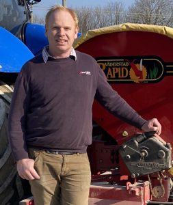
Towards the end of 2021, we were contacted by a farmer in Dorset, to buy Mueller Elektronik kit to help him facilitate a refurb, rebuild and modernisation of his Vaderstad 30s Drill. As if the work involved in a mixed arable and Aberdeen Angus beef farm wasn’t enough, the restorative undertaking began mid-November and was no mean feat. With countless hours and tireless dedication to the cause, Jamie Hawkins logged the whole project and kept followers on The Farming Forum intrigued and interested with his progress posts.
We thought his story was inspiring and insightful, so we suggest you find a quiet space for yourself, and here it is, in his own words, for you to enjoy.
The sensible thing would be to replace the drill for something newer, but I happen to really like it for many reasons including, seed placement and its ability to cope with many varied conditions including wet and sticky conditions compared with heavier trailed drills. I also like the fact that as it is mounted it follows the tractor more accurately on sidling ground, also because its different and quirky I seem to pick up lots of contracting work with it.
The plan is to strip the drill down completely, repair any broken components and have everything shot blasted and powder coated before reassembly with new parts as necessary. Part of the rebuild will be to convert the mechanical wheel driven metering to motor driven controlled through ISOBUS this will hopefully allow me to use variable rate seeding as well as section control for the headlands.
I am slightly cheating as I have already started this project in the late spring and am just starting to put it back together, this meant I had to borrow a drill for the autumn drilling which wasn’t ideal but hopefully it will be ready for the spring barley.
Which system are you using for the ISOBUS conversion?
I have chosen to use the Mueller system; I don’t know how it compares to other kits, but it looked good and seemed relatively good value.
One thing they (SoilEssentials) were slightly concerned about was the motor having enough torque to drive a box drill metering system, so I had to measure the start torque with a torque wrench. It seemed like it would cope, so keeping my fingers crossed!
One thing that caused a bit of a headache was working out how to get the drive to the metering shaft. I eventually decided to take the easy option and run through the original drill variable speed gearbox. Whilst this has the potential to cause speed variation issues, it is a remarkably straightforward way to connect the motor. The drill has always been perfectly accurate, so hopefully this should not be an issue.
We have a particularly good local company that will take a sketch and put it onto a CAD drawing before laser cutting and folding. I have used them previously, so I got them to make a motor mounting bracket.
Did you foresee any particular challenges with this model?
It’s a lovely drill to use but the chassis cracking, and metal fatigue found on many of these models is a problem and probably explains why it was discontinued. I also think it must have been expensive to make for a 3m box drill. I have re-welded mine and have made some bracing plates as well which I’m hoping will make it stronger.
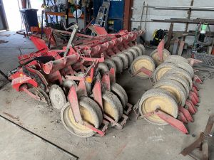
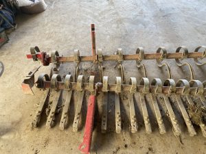
The next step and potentially the most daunting was to strip it right back to all the individual components and make a list of parts to be repaired and new parts to be ordered. The discs, coulters and bearings were all pretty worn so they went on the new parts list, as well as a new set of following Harrow tines. The tine beam has always been a weak component so I changed over to the newer type tines that can be mounted onto the 40mm box. Apart from a set of wheel axle bushes, the only other thing for the Vaderstad parts list was a new set of decals for when it looks shiny again.
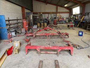
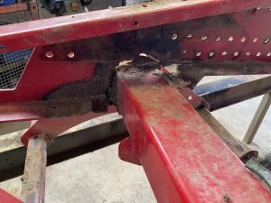
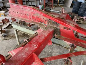
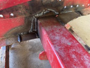
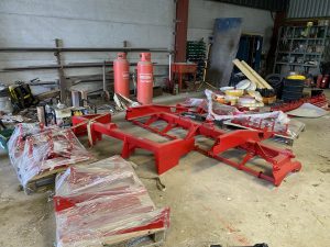
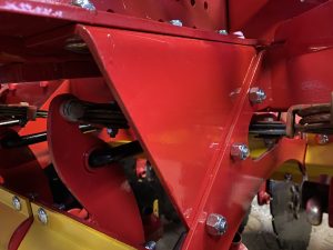
Now the drill was in bits I was able to get in and sort the chassis out. You can see in the photos the coulter carriage has completely cracked away from the main frame. The best plan of action was to re-weld it to the best of my abilities, but also add some stress plates to take some of the strain, rather than have all the force trying to twist the only 4-inch box section the coulters are suspended from.
I have had two more plates cut and folded to which I have drilled extra holes in the main frame and chassis, so hopefully these will take a bit of the chassis stress in the future.
All the other components were in pretty good condition apart from the wheel rims which had worn on the outer rims. These wheels only appear to come with new tyres and are awfully expensive, so I repaired the originals by rolling 8mm rod into rings and welding them to the outside of the rims.
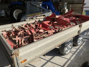
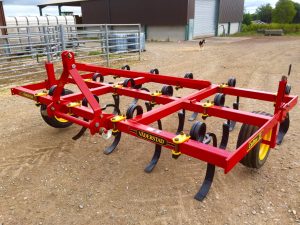
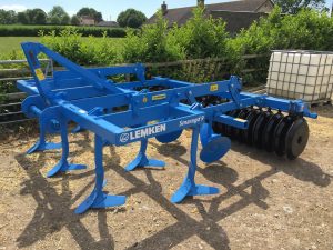
I’ve had my own shot blaster for years and I have included some photos of previous cultivators I have reconditioned here, so I’m fully aware of the work involved in shot blasting and painting. The plan was to do this myself, until I saw the pile of components to be painted. Whilst this really is a small drill, my 16ft trailer was filled to the brim with the red parts, but this didn’t include the hopper or yellow and black parts which also amounted to another full trailer load!
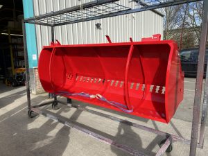
I have started using a local powder coating company for other engineering interests and having seen how easy it is to paint on their production line this seemed a much better option. For anyone who hasn’t seen it done, the process starts in a heat oven where all components have the original paint burnt off (a huge bonus to anyone who has tried blasting Vaderstad paint in the past!). It is then cleaned in a blast room to remove any residue before a quick coat of etch primer. Everything is put on racks and charged with a negative charge whilst the powder spray gun has a positive charge – as the powder is sprayed at the metal parts, the powder flows around the object sticking an even coat all over. The powder is baked on before being nicely wrapped and returned looking like new.
To get the correct colours, we matched up several new components as good examples of the original colours. I always thought Vaderstad changed their red a few years ago as the newer kit is a slightly brighter red than it used to be. An original unfaded part of the drill showed the colour used to be BS 538 whereas the new colour is Ral 3002 – these colours are quite close, but I wanted to keep the original red, seeing as the only new components were coulters and following tines. Bs538 is the shade I used. There were many different yellows used in the early days, but I think it’s signal yellow Ral 1003 used now which is what I used. The black, we used Ral 9005 jet black. To avoid confusion, I took the assorted colours in separately. The yellow and black going first before the first trailer load of red.
The workshop is starting to fill up with shiny parts to go back together. There is still one more trailer load of red parts as well as the hopper to be powder coated yet. I have also sent the zinc parts off to be re-plated, partly to fill a minimum order quantity for another project, but it does look smart coming back with the yellow passivate finish. The order of the new Vaderstad parts has also arrived.
Was there a modification option to strengthen the chassis?
Yes, the modification was a stronger headstock. I think mine must have been modified at some point as it has the later type of headstock, but the serial plates have been pop riveted back on rather than the cold rivets from the factory.
I’ve found the depth control to be very accurate on it. One thing that alters the depth considerably, is the top link length as this can alter seeding depth from the front and rear coulters. Once I found the correct length, I counted the top link turns and wrote it on the headstock. I do this on all my implements as it saves time setting up in the field.
The wheels have gone back together. All the bushes’ seals and bearings had a 3-week soak in de-greaser before being lightly oiled and lithium grease sprayed into the bearings before assembly.
Why did you re-use the bearings?
There was nothing wrong with the originals and they are also high quality, so it was money I didn’t need to spend. The disc bearings were very worn and replaced, but I have never changed a wheel bearing on it.
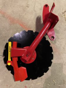
I thought I would show a picture of the disc and coulter going back together as it shows a couple of things. Firstly, it’s a direct comparison of the two reds used, the coulter is finished in the new brighter red. Secondly, it shows how the coulter position is adjusted by a sliding spring rather than the two bolt arrangement on the trailed drills. Since these mounted versions have some negative points highlighted by others, I thought I would share some of the advantages I have found with my ownership of the drill. The first one being its ability to cope with wet and sticky conditions. By sliding the coulter to its lowest position on the disc will give the most accurate seed placement, however if conditions get wet and sticky you can slide the coulter up the disc creating less resistance on the disc enabling them to turn more easily allowing soil to flow though without stalling. Although you can do this on a trailed drills, it is made very quick and easy with the slider system. Secondly, if you hit a wet hole, you can lift the drill on the hydraulics a bit until you have passed it making it a very capable machine for sticky conditions. The other advantages are no punctures with the Otico tyres, and I like the lightness of the whole system matched up to a small tractor on wide tyres. The other advantage is our farm is on a few quite steep rolling hills so trailed drills tend to hang down on the slopes, but a mounted drill can be tightened on the stabilising bars and hold a straighter line. I also like the simplicity of it, although that’s a bit controversial now with the ISOBUS conversion but at least if it is me fitting it, I will hopefully have a good understanding of it!
This stage has taken a bit of time. Firstly, I went down with the dreaded Covid so couldn’t get in the workshop for 10 days. Once I got back to it, I managed to get this far before realising I had two cir-clips that hold the bearings on, left! So had to strip it down again to find out where they were missing. It’s been a struggle, but the main chassis is rebuilt with new discs bearings and coulters.
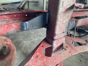
Now the headstock is starting to go back together and this is a good opportunity to show the new stress plates I am adding to hopefully reduce the twisting stress in the main centre box section of the chassis. I was already having laser cutting and folding done so I had these plates added to the order – they were drilled and pre-fitted to the drill, before powder coating, making them easy to add in during the rebuild.
Progress has been a bit slow since my last post, Christmas and other work pressures seem to have got in the way, however the chassis is all built-up and ready to have the hopper fitted back when it returns from the powder coaters who are suffering like everyone one now with staff shortages. No-one has started spring drilling in this area yet, and I know I’m not going to get the ISOBUS on for this season, but I’m still hoping that now I may get the hopper in time to test the rebuilt drill with the original land wheel.
There is a lot of value in rebuilding old kit. The shot blasting and powder coating doesn’t earn you any more money but unfortunately, I like shiny new paint!
I have just collected the hopper, the weather for next week is looking good. So, the pressure is on!
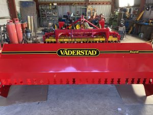
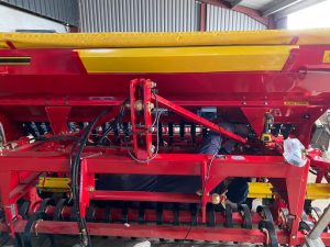
I have had a good day on it today and made some great progress. The hopper is back on with all the metering mechanisms fitted.
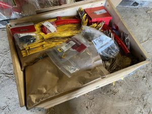
The drill is now at a stage where I can refit the old land drive wheel and go drilling. However, the weather hasn’t turned out as good as forecast so I have started to look at the ISOBUS kit that has been sitting in a box for nearly a year. The photo shows all the components that in theory you connect to existing sensors and tramline clutches and then join to give the drill ISOBUS. The kit is a Mueller Elektronik Drill Controller with the first job to find the correct-sized sprocket to fit onto the motor.
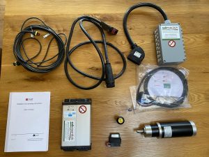
The motor looks very small, will it be sufficient?
It has a start-up torque of 7.2NM. It’s a bit close to the limit, but hopefully with the correct gearing it should be sufficient. I have worked the gearing to enable the motor to use the higher rpm of the motor. It’s running through the original variable speed gearbox to enable fine tuning. To be fair to the company I bought the kit from (SoilEssentials) – they did discuss the motor torque at the time. I assessed the torque requirement by putting a mini torque wrench onto the drive sprocket and felt it should work. However, this will be quite different during operation in the real world. This is the problem with projects like this you don’t really know until you try it. I hope it will work… otherwise I shall be back to the land wheel with an ISOBUS kit for sale!
Which company did you buy the ISOBUS kit from?
I bought it from SoilEssentials who are authorised resellers for Mueller Elektronik.
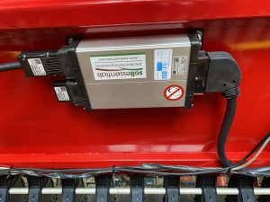
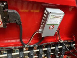
I decided to fit the boxes directly underneath the hopper as I know this has always been a relatively clean and dry place. However, getting in position to fit them was rather painful and somewhat tricky!
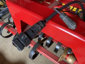
The first part of the system is the ISOBUS plug, this connects the tractors ISOBUS socket and the job computer. The other plug is an ISO11786. I used this so as the tractor could supply the speed signal and work position signal without the need for a separate radar and position sensor.
The next component is the job computer – this was programmed especially for my requirements to provide the functions I needed to control the drill. The cable comes from the tractor with a CAN terminator underneath. The cable then runs to the junction box.
The junction box connects the job computer to the various sensors and actuators. The inputs for this application are radar speed and hitch position supplied from the tractors Iso11786 socket, tank level sensor, motor speed and a motor run switch for calibration. The outputs are for the tramline clutches and the drive motor.
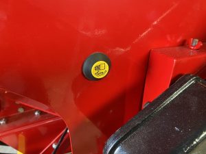
Calibration switch to run motor to fill trays.
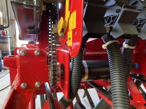
The motor as fitted! Unfortunately, I had to modify my mounting bracket as it was in the way of a linkage rod underneath as well as the drive chain. I connected it up to the original variable speed drive gearbox with a new sprocket and chain. The one worry was the motor wasn’t going to have enough torque to run the metering system for a box drill, but I have been testing this afternoon and it appears to be capable of doing so. I filled the hopper with wheat and set the gearbox at mid-ratio (the higher the ratio the more torque is required to drive it). It easily delivered 180kgs at 10kmh, I then wound the gearbox right up and the motor was able to start easily from low speed all the way to delivering 300kgs at 12.8kmh, which I doubt I will ever do. Obviously, it still needs testing in the field but I am feeling more confident about it now.
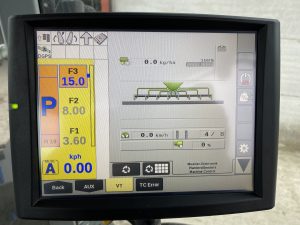
This is how the drill comes up on the tractor’s screen. All the functions have been tested and working. I’m looking forward to having a go with it now!
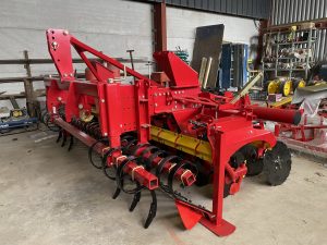
Apart from waiting for two decals that depict the model, the drill is now finished and ready to come out of the workshop. As soon as the weather brightens up, I will get it out for the final photo shot and work out how much it has cost me to do!
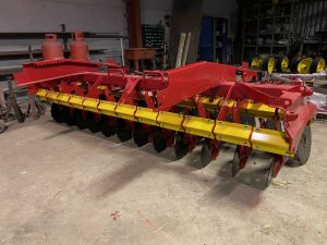
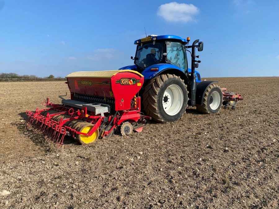
Finally, a bit of sunshine to take photos.
So, Project 331 is now finished, apart from the ‘30s’ model decals which are on back order. I have also updated the following harrow to the carrier drill type, mainly because I can use standard 40mm box for the beam as it was cheaper to replace.
First try, teething troubles and thank-yous
So, with the drill finished and the weather ready I have taken Project 331 out for its first field test. I would have loved to say everything was fine, but as anyone who has ever done a rebuild like this knows there is always a teething troublesome somewhere! Although I had tested most of the workings on the drill, I hadn’t checked if the ‘hydraulics raised’ signal from the ISO11786 was switching the drill on or off. I calibrated the drill which was extremely easy with the button and electric motor, drove out to the field, only to discover that the motor ran when the drill was raised but as soon as you lowered it into work, the motor stopped turning. The screen had options to choose between the socket signal, tractor CAN signal via ISOBUS or run all the time. I selected CAN signal – this supplied a speed signal, but not implement lift signal. I then tried using a 12v switch-over relay with the signal from the socket, however the signal from the socket didn’t provide enough current to switch the relay over. I then had to give in and call SoilEssentials (who I bought the drill controller from) for some help!
Although I am mechanically minded and have a basic understanding of vehicle electrics, I have not had a lot of experience with precision farming systems. It turns out this Mueller drill controller has many more functions than just ISOBUS. It is what is sometimes termed as ‘smart implement control’. This is where the implement sends information to the tractor screen for the tractor to be able to control the implement. To get the most out of it I needed to unlock ‘task controller’ on the tractors screen. I know this technology is common, especially on sprayers and spreaders, but I had never used it. There is a 10-day free trial of Task Controller that I unlocked just to check everything worked ok before I bought it. Once this was unlocked, SoilEssentials helped me set it up on the tractor as they had already pre-programmed the controller for me. Suddenly, with that bit of help, everything was up and running and the tractor was talking to the controller as it should. I created a headland boundary on the screen and with the boundary controller switched on, the drill started to seed. As I crossed the boundary line at the other end of the field it stopped seeding. Suddenly drilling has just got easier and a whole lot more accurate. After the teething troubles the drill ran a treat to the end. The sound has changed from ‘clattering to chattering’ where everything is new and tight. The top link now sits a full 11 turns shorter where the cracks have gone, and the carriage used to drag backwards. It really was like using a brand-new machine! Once set-up correctly the ISOBUS kit worked without fault and the motor didn’t even get warm. The biggest bonus was how accurately the field drilled out. The drill has always been accurate in the fact it sows the correct number of seed for the area on the screen, but as we all know fields always drill out more than they are. The ‘swath’ working width is set for approximately a 4% overlap and when this was considered the area and seed used were spot on accurate.
I’m really pleased with how the drill went and there are lots of people to thank. But I would particularly like to mention SoilEssentials for letting me have the ISOBUS kit as a diy solution. Normally they only supply and fit these kits in their area but after a long chat on the phone they agreed I had enough engineering experience to supply one as a kit. It fitted with ease, and they also need a thank you for helping me with the teething trouble and programming over the weekend.
They have also now sent me, unexpectedly and by surprise, a new ISO11786 lead containing a chip to convert the linkage signal, in case I want to use it on a tractor without Task Controller.
What are the benefits of this rebuild?
The lower cost against a new drill is obviously a big part of a rebuild, but the other benefit is now I know that machine inside out. When problems occur, or maybe even before they become problems, I can sort them without wasting time and money trying to diagnose things. That’s where it can be more difficult on modern equipment – diagnosing the problem.
So many times, you look at a new machine and wonder where to start with diagnostics. On this, I feel I can go into the screen and diagnose sensors and signals. It’s also an old machine I know like the back of my hand. Then consider the back-up support from SoilEssentials for the job computer and Vaderstad for their good parts back-up for older machines. I am confident it should be a fairly futureproof investment.
A little bit extra
Jamie, who has a background in agricultural engineering, was looking for ways of improving the quality of ride in his own tractor and set about designing and building an air suspension kit. Fast forward through development and testing stages he now has a fully operational business supplying an additional income stream: Case & New Holland air suspension upgrade kits – Superglide Suspension https://www.superglidesuspension.com/